In today’s industrial automation landscape, the need for faster and longer-distance network communication is ever-increasing. While traditional electrical signal communication has its limitations in terms of transmission distance and speed, optical signal communication is gaining popularity due to its advantages like low transmission loss and strong anti-interference capabilities, making it ideal for long-distance transmission.
However, serial communication, particularly RS232, still plays a crucial role in many industrial settings. Let’s take a closer look at RS232 and its key aspects:
1. The History of RS232
RS232 was introduced in 1962 by the Electronic Industries Association (EIA) as a communication standard. Its full name is “Electrical Characteristics of the Interface Between Data Terminal Equipment and Data Communication Equipment.” Over the years, it has undergone several revisions:
– 1969: Version C (RS232-C)
– 1986: Version D (RS232-D)
– 1991: Version E (RS232-E)
– 1997: Version F (RS232-F)
Today, RS232 is commonly used for communication between PLCs and devices like touch screens, card readers, barcode scanners, and printers.
2. RS232 Interface
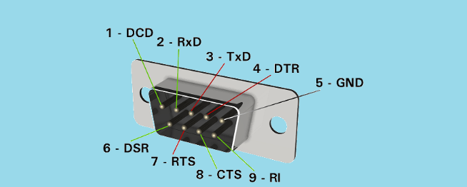
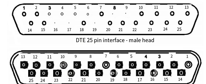
 Prior to the F version, RS232 used a 25-pin serial interface, available in both male (for DTE devices) and female (for DCE devices) configurations. The F version introduced a simplified 9-pin interface, which is more commonly used now.
In industrial automation, PLCs are typically considered DTE devices and use male connectors. For example, the Siemens S7-1200 serial module CM1241 RS232 uses a male connector.
For DTE-to-DTE communication (like between a PLC and a barcode scanner), a crossover or “null modem” cable is used, where the transmit and receive lines are crossed.
3. RS232 Electrical Signals
RS232 uses voltage signals relative to a common ground (GND). A voltage between +3V and +15V represents a logical “0”, while a voltage between -3V and -15V represents a logical “1”. Voltages between -3V and +3V are undefined. In practice, voltages between ±5V and ±15V are preferred for reliable communication.
4. RS232 Voltage Level Conversion
Microcontrollers typically use TTL voltage levels, which need to be converted to RS232 levels. This is done using specialized converter chips like the MAX3232 from TI or ST3232 from ST Microelectronics.
5. RS232 Data Transmission
Data transmission in RS232 involves several key concepts:
a) Baud Rate: This is the number of signal changes per second. Common baud rates include 9600, 38400, 56000, and 115200 bps.
b) Data Frame: An RS232 data frame consists of:
– Start bit (1 bit)
– Data bits (typically 7 or 8 bits)
– Parity bit (0 or 1 bit for error checking)
– Stop bit(s) (1, 1.5, or 2 bits)
For example, with settings of 9600 baud, 8 data bits, no parity, and 1 stop bit (often written as 9600 8N1), each frame is 10 bits long. This means you can transmit up to 960 bytes of actual data per second (9600 / 10 = 960).
Understanding these aspects of RS232 communication is crucial for effectively implementing and troubleshooting serial connections in industrial automation systems. While newer technologies are available, RS232 remains a reliable and widely used standard in many industrial applications.
 KEY-IOT
 Prior to the F version, RS232 used a 25-pin serial interface, available in both male (for DTE devices) and female (for DCE devices) configurations. The F version introduced a simplified 9-pin interface, which is more commonly used now.


